Estimated Delivery Date: Wednesday, July 1


Trackable Worldwide Shipping

Love It or Get a 100% Refund!
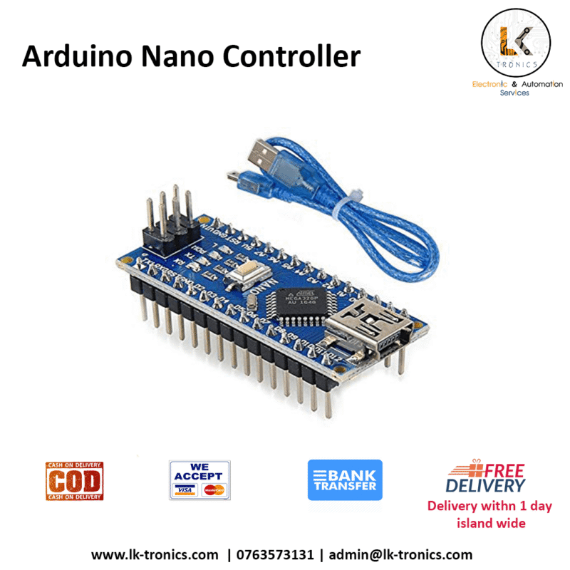
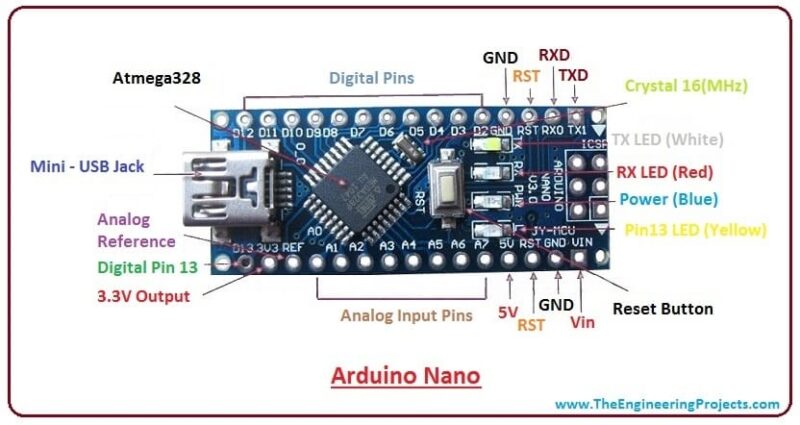
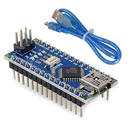
Arduino Nano Controller ATmega328PGet the best from the very right place Arduino Nano Controller ATmega328PArduino Nano Pin ConfigurationPin CategoryPin NameDetailsPowerVin, 3.3V, 5V, GNDVin: Input voltage to Arduino when using an external power source (6-12V).5V: Regulated power supply used to power microcontroller and other components on the board.3.3V: 3.3V supply generated by on-board voltage regulator. Maximum current draw is 50mA.GND: Ground pins.ResetResetResets the microcontroller.Analog PinsA0 – A7Used to measure analog voltage in the range of 0-5VInput/Output PinsDigital Pins D0 – D13Can be used as input or output pins. 0V (low) and 5V (high)SerialRx, TxUsed to receive and transmit TTL serial data.External Interrupts2, 3To trigger an interrupt.PWM3, 5, 6, 9, 11Provides 8-bit PWM output.SPI10 (SS), 11 (MOSI), 12 (MISO) and 13 (SCK)Used for SPI communication.Inbuilt LED13To turn on the inbuilt LED.IICA4 (SDA), A5 (SCA)Used for TWI communication.AREFAREFTo provide reference voltage for input voltage. Arduino Nano Technical SpecificationsMicrocontrollerATmega328P – 8 bit AVR family microcontrollerOperating Voltage5VRecommended Input Voltage for Vin pin7-12VAnalog Input Pins6 (A0 – A5)Digital I/O Pins14 (Out of which 6 provide PWM output)DC Current on I/O Pins40 mADC Current on 3.3V Pin50 mAFlash Memory32 KB (2 KB is used for Bootloader)SRAM2 KBEEPROM1 KBFrequency (Clock Speed)16 MHzCommunicationIIC, SPI, USARTDifference between Arduino Nano and Arduino UNONameProcessorOperating/Input VoltageCPU speedAnalog In/OutDigital IO/PWMEEPROM / SRAM[kB]FlashUSBUSARTUnoATmega328P5V / 7-12V16 MHz6 / 014 / 61 / 232Regular1NanoATmega328P5V / 7-12V16 MHz8 / 014 / 61 / 232Mini1Difference between Arduino Nano and Arduino MegaThere is a considerable amount of difference between the Arduino Nano and the Arduino mega as the processor used itself is different. Arduino Mega is more powerful than an Arduino Nano in terms of speed and number of I/O pins. As you might guess the size is also bigger than an Arduino UNO. Arduino Mega is normally used for projects which require a lot of I/O pins and different Communication protocols. The technical difference between Nano and Mega is shown below.NameProcessorOperating/Input VoltageCPU speedAnalog In/OutDigital IO/PWMEEPROM / SRAM[kB]FlashUSBUSARTMegaATmega25605V / 7-12V16 MHz16 / 054 / 154 / 8256Regular4NanoATmega328P5V / 7-12V16 MHz8 / 014 / 61 / 232Mini1Understanding Arduino NanoThe Arduino Nano Controller ATmega328P board is designed in such a way that it is very easy for beginners to get started with microcontrollers. This board especially is breadboard friendly is very easy to handle the connections. Let’s start with powering the Board.Powering you Arduino Nano:There are totally three ways by which you can power your Nano.USB Jack: Connect the mini USB jack to a phone charger or computer through a cable and it will draw power required for the board to functionVin Pin: The Vin pin can be supplied with a unregulated 6-12V to power the board. The on-board voltage regulator regulates it to 5V 5V Pin: If you have a regulated 5V supply then you can directly provide this o the 5V pin of the Arduino.Input/output:There are totally 14 digital Pins and 8 Analog pins on your Nano board. The digital pins can be used to interface sensors by using them as input pins or drive loads by using them as output pins. A simple function like pinMode() and digitalWrite() can be used to control their operation. The operating voltage is 0V and 5V for digital pins. The analog pins can measure analog voltage from 0V to 5V using any of the 8 Analog pins using a simple function like analogRead()These pins apart from serving their purpose can also be used for special purposes which are discussed below:Serial Pins 0 (Rx) and 1 (Tx): Rx and Tx pins are used to receive and transmit TTL serial data. They are connected with the corresponding ATmega328P USB to TTL serial chip.External Interrupt Pins 2 and 3: These pins can be configured to trigger an interrupt on a low value, a rising or falling edge, or a change in value.PWM Pins 3, 5, 6, 9, and 11: These pins provide an 8-bit PWM output by using the analogWrite() function.SPI Pins 10 (SS), 11 (MOSI), 12 (MISO) and 13 (SCK): These pins are used for SPI communication.In-built LED Pin 13: This pin is connected with an built-in LED, when pin 13 is HIGH – LED is on and when pin 13 is LOW, its off.I2C A4 (SDA) and A5 (SCA): Used for IIC communication using Wire library.AREF: Used to provide reference voltage for analog inputs with analogReference() function.Reset Pin: Making this pin LOW, resets the microcontroller.These special functions and their respective pins are illustrated in the Arduino nano pin diagram shown above.How to use Arduino Nano Controller ATmega328PIt will hardly take 5-10 minutes to upload you first program to Arduino Nano. All you need is the Arduino IDE a USB cable and your Nano board itself.Download and Install Arduino:The first step would be install the Arduino IDE which is available for download for free from the below link. After installing Arduino you might also want to install the drivers (link given below) for your Arduino to communicate with your ComputerArduino IDE DownloadDriver DownloadUploading your first programOnce arduino IDE is installed on the computer, connect the board with a computer using a USB cable. Now open the Arduino IDE and choose the correct board by selecting Tools>Boards>Arduino/Nano, and choose the correct Port by selecting Tools>Port. Arduino Uno is programmed using Arduino programming language based on Wiring. To get it started with the Arduino Uno board and blink the built-in LED, load the example code by selecting Files>Examples>Basics>Blink. Once the example code (also shown below) is loaded into your IDE, click on the ‘upload’ button given on the top bar. Once the upload is finished, you should see the Arduino’s built-in LED blink. Below is the example code for blinking:// the setup function runs once when you press reset or power the board void setup() { // initialize digital pin LED_BUILTIN as an output. pinMode(LED_BUILTIN, OUTPUT); } // the loop function runs over and over again forever void loop() { digitalWrite(LED_BUILTIN, HIGH); // turn the LED on (HIGH is the voltage level) delay(1000); // wait for a second digitalWrite(LED_BUILTIN, LOW); // turn the LED off by making the voltage LOW delay(1000); // wait for a second }Applications of Arduino Nano Controller ATmega328P Prototyping of Electronics Products and SystemsMultiple DIY Projects.Easy to use for beginner-level DIYers and makers.Projects requiring Multiple I/O interfaces and communications. SKU: LKMIC00001 Categories: Arduino, Microcontrollers Tags: Arduino, Arduino Nano, Arduino Nano Controller ATmega328P, near me


FREE DELIVERY
On all orders

FREE RETURNS
No questions asked return policy

NEED HELP? [email protected]
E-mail us with any questions or concerns

MONEY BACK GUARANTEE
Worry-free shopping